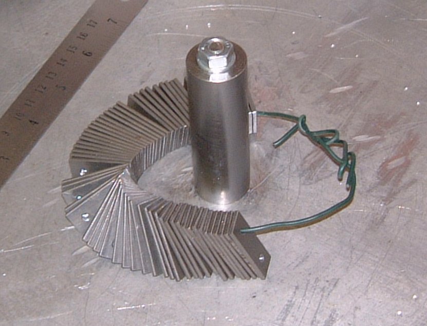
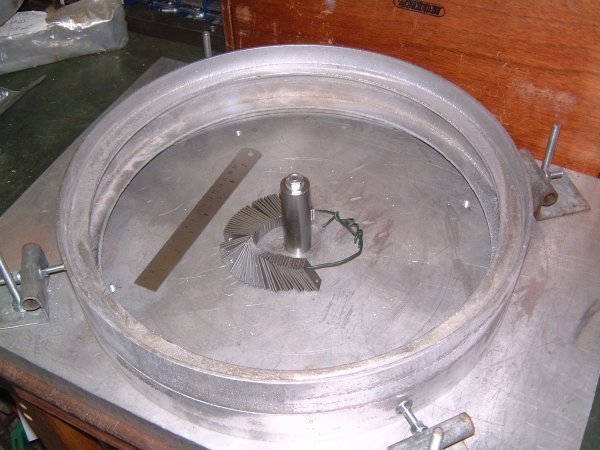
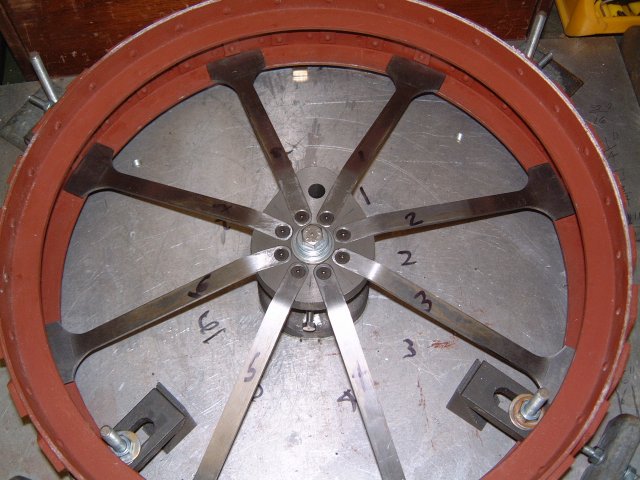
The left hand image shows the wheel jig with rim centralising bolts
in place.
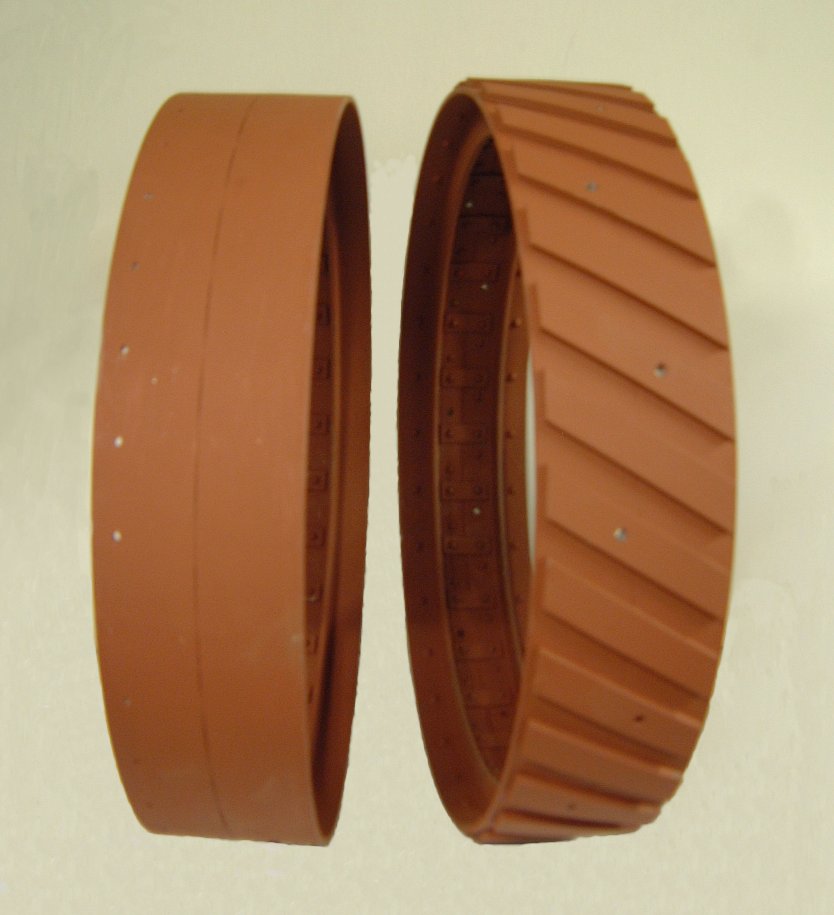
The right hand image shows the wheel jig with single rim in place.
|
|
|
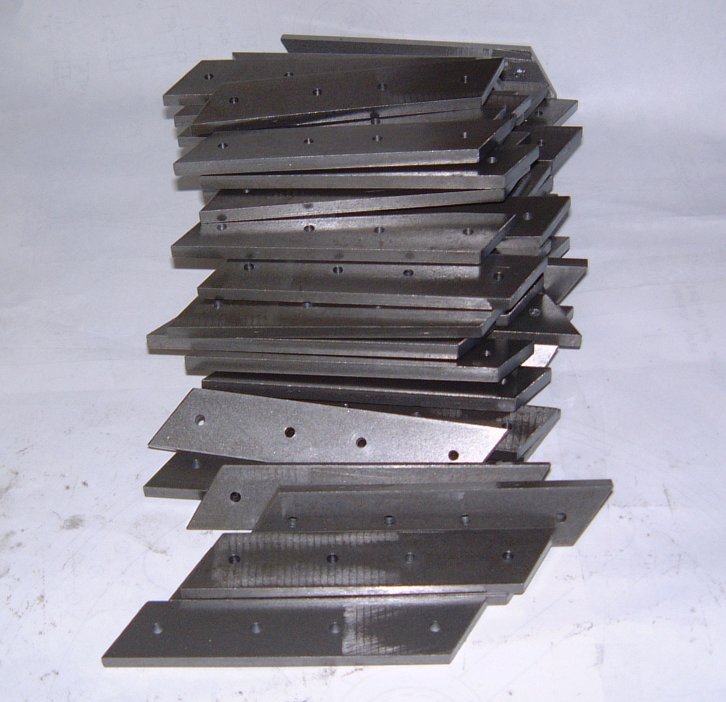
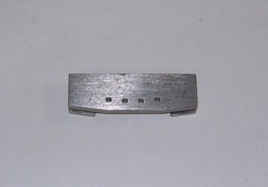
The left hand image shows the wheel rim tie plates, all 64 of them
(plus a few spares). Manufacturing these rates very highly on the
tedious job list!
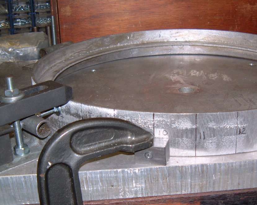
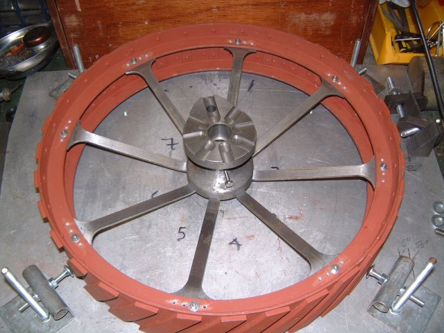
The right hand image shows the wheel jig with a pair of rims prior
to drilling and fitting the tie plates.
|
|
|
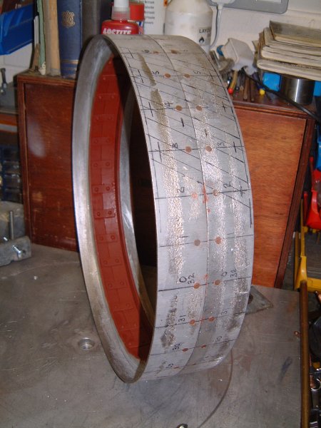
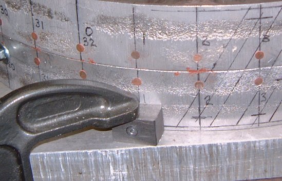
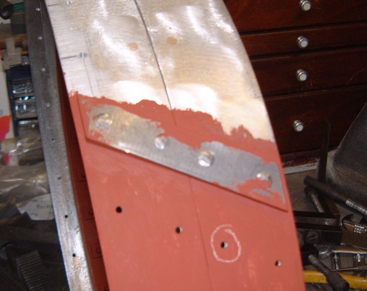
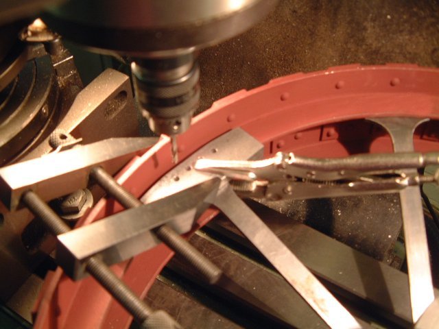
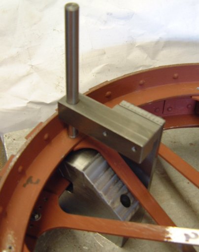
The left hand image shows the wheel jig with drill block in place
ready for drilling guide set of holes for ties (note the lines marking
equal thirty-seconds of the wheel circumference).
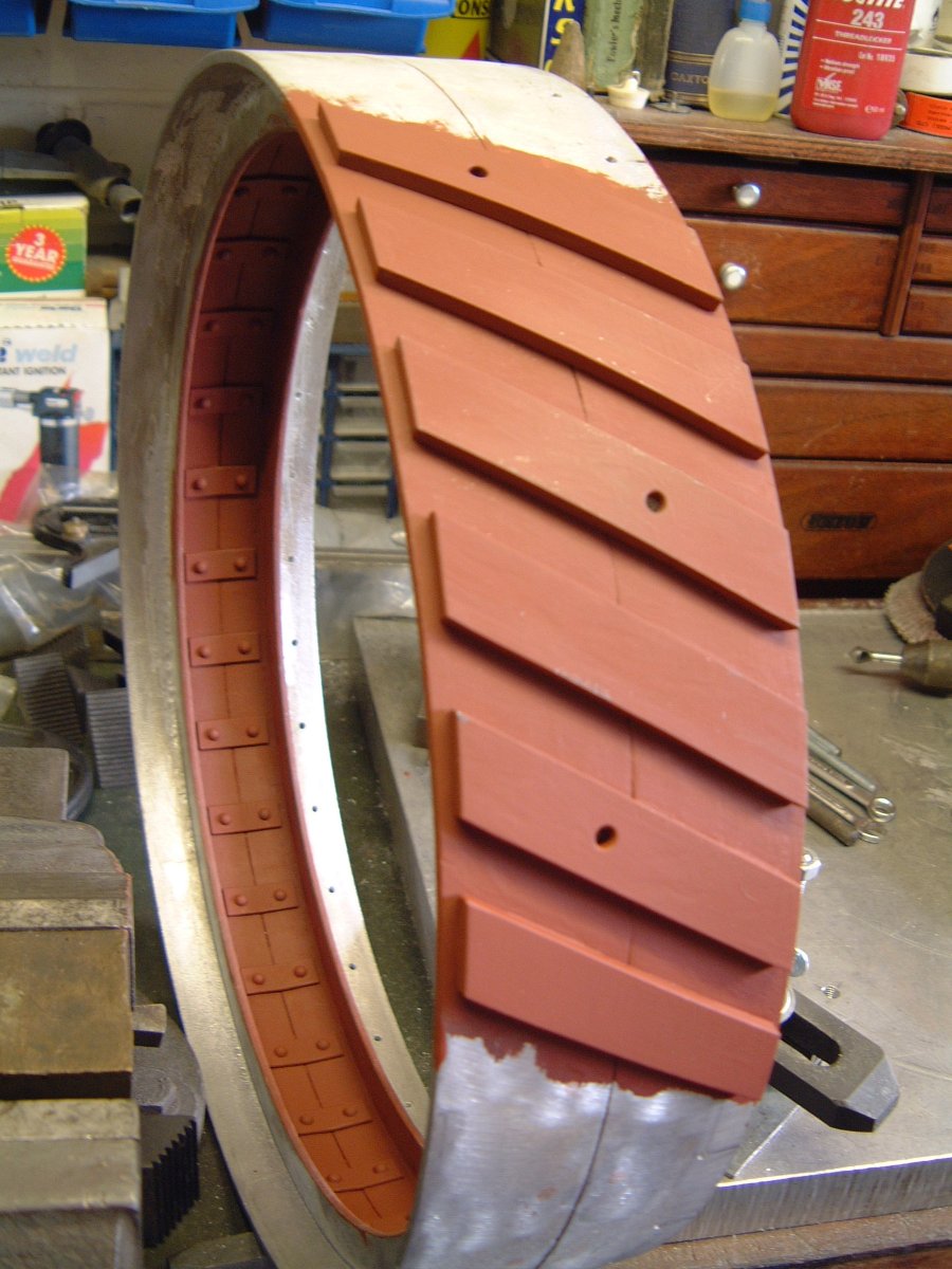
The right hand image shows the completed wheel with all ties riveted.
|
|
|
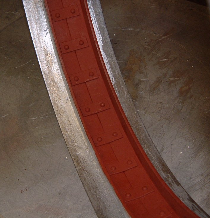
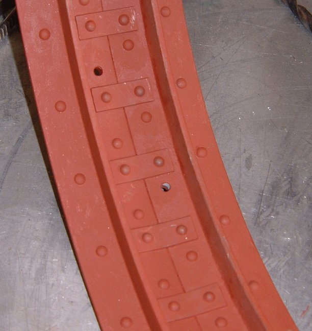
The left hand image shows a close up of the finished wheel ties.
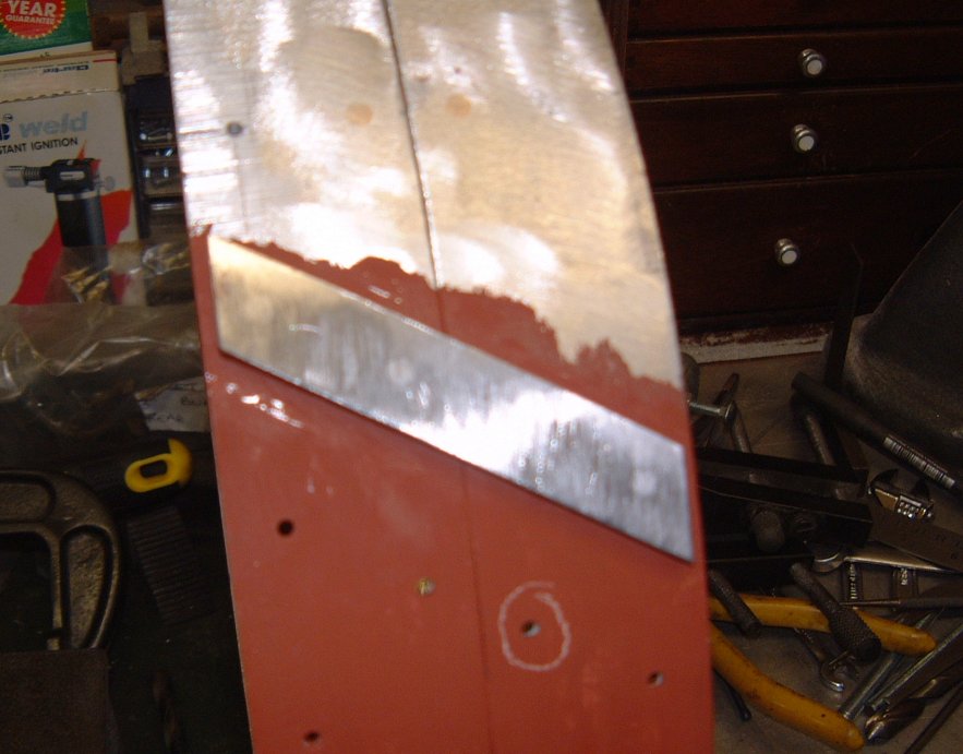
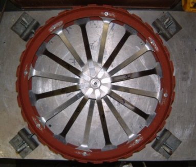
The right hand image shows the jig set up for drilling the lining
up holes for the strakes. Having learned from my mistakes, I will
be fitting the strakes before I fit the spokes!
|
|
|
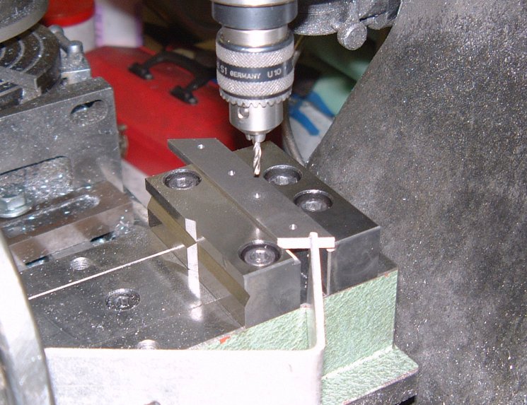
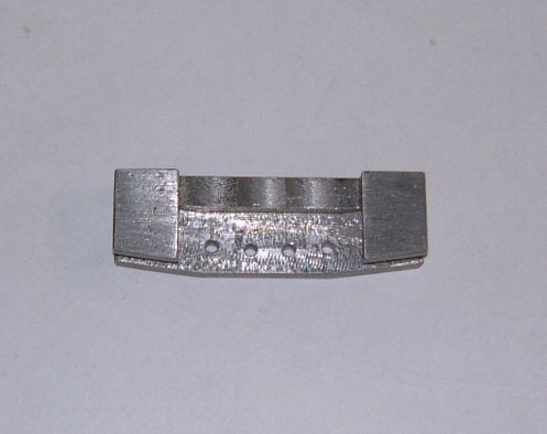
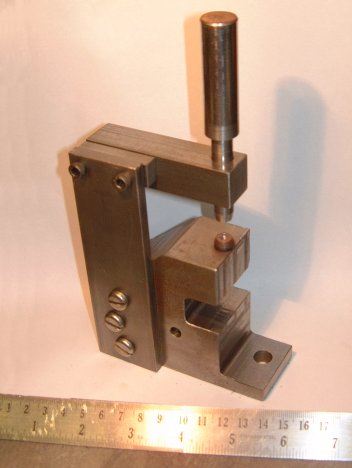
The left hand image shows the lashed-up jig stop for drilling the rivet holes in the strakes.
The right hand image shows the completed strakes all 66 of them
(64 plus 2 spares).
|
|
|
The left hand image shows the first strake riveted.
The right hand image shows the dressed strake.
|
|
|
The left hand image shows the first six strakes completed (note
the spud fixing holes in alternate strakes).
The right hand image shows a close-up of the rivet heads.
|
|
|
On the left - Half way there, 32 strakes down, 32 to go!
On the right - A complete pair of wheel rims ready for spoking up.
|
|
|
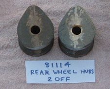
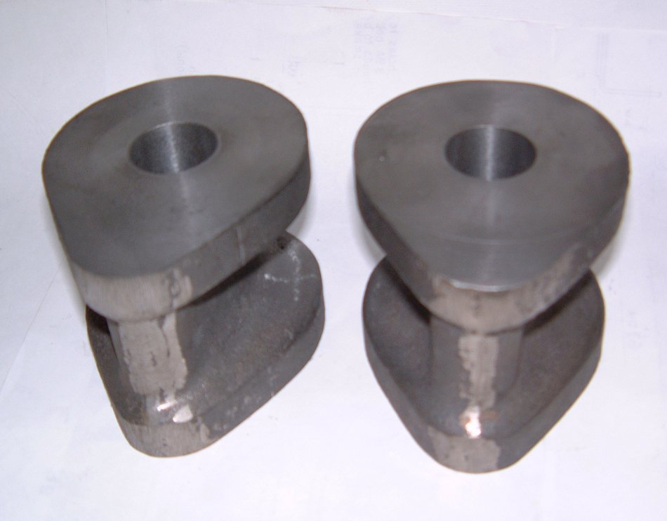
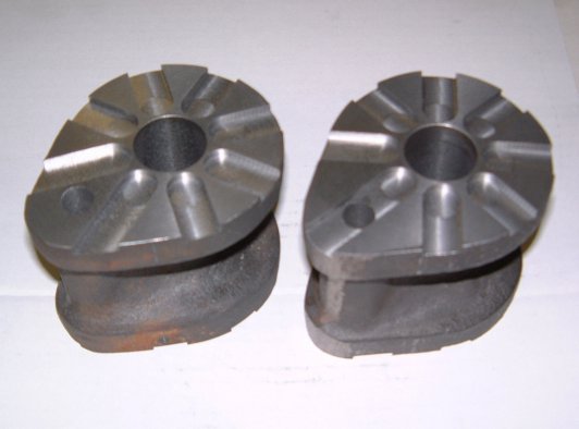
On the left - The rear hubs bored and faced
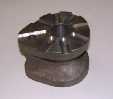
On the right - A rear hub drilled for the drive pin and milled for the spokes.
|
|
|
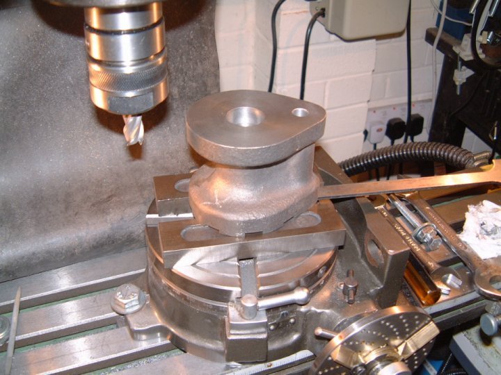
On the left - The rear hub is being set up for milling the opposite
face slots. The hub is lined up with the spoke and then advanced half
of the spoke angle.
On the right a finished pair of hubs showing alternate faces.
|
|
|
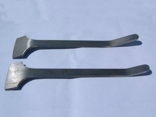
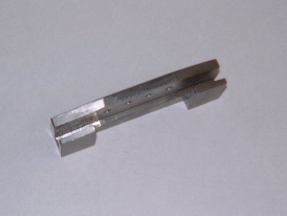
On the left - The spoke bending set-up.
On the right a finished pair of bent spokes (one of each length).
|
|
|
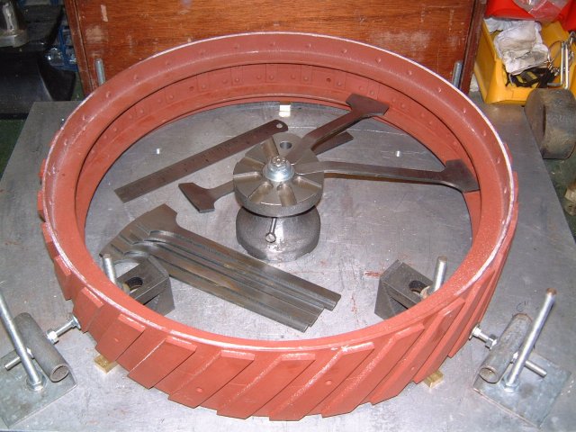
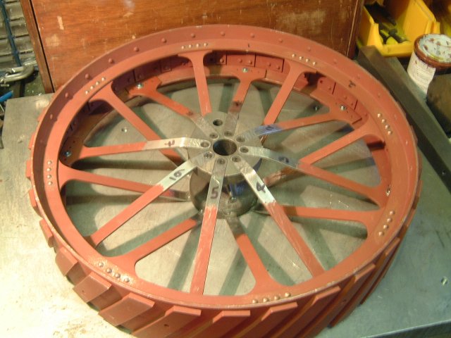
On the left - One of each spoke length fitted.
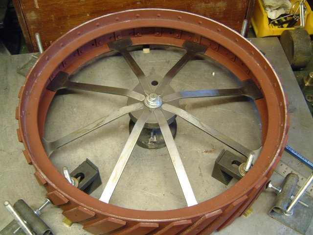
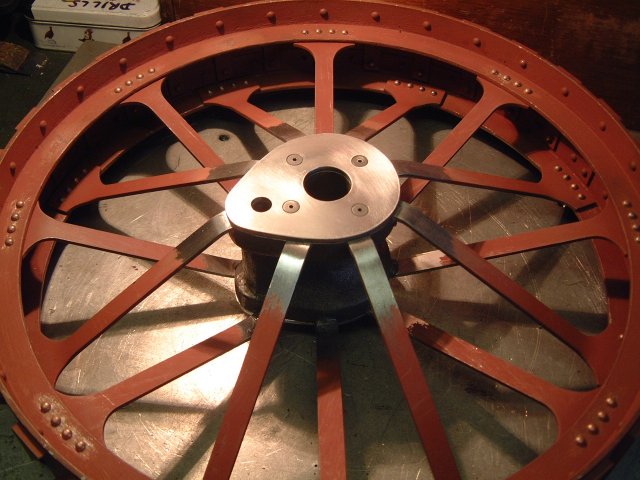
On the right all spokes have been fitted.
|
|
|
On the left - Hub drilled and tapped and eight 2BA CSK SKT Head screws fitted.
On the right - Top view of spoke palm drilling jig.
|
|
|
On the left - Bottom view of spoke palm drilling jig.
On the right - Edge view of spoke palm drilling jig.
|
|
|
On the left - Drill jig in-situe (Note engineer's clamp and 'Mole' grips used to hold jig in place).
On the right - Holes drilled and temporary bolt in place.
|
|
|
On the left - First wheel turned over on jig ready for spoking the other side.
On the right - First wheel with full set of spokes fitted.
|
|
|
On the left - Riveting jig - rule is in the picture to give scale.
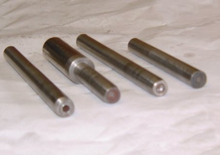
On the right - The four riveting sets as used.
|
|
|
On the left - Riveting jig in situe.
On the right - First four rivets finished.
|
|
|
On the left - First side of first wheel completely riveted.
On the right - Completely riveted wheel showing inner hub plate
fitted.
|
|
|
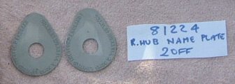
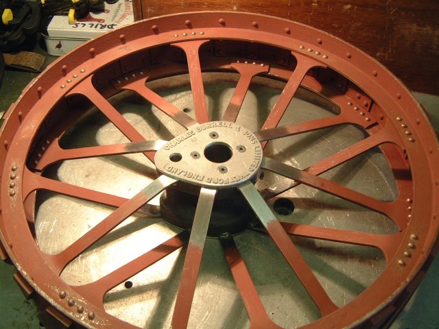
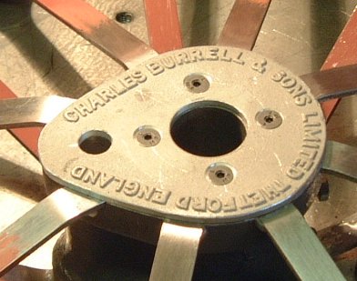
On the left - Completely riveted wheel showing outer hub plate fitted.
On the right - Close-up of outer hub plate showing the 'Charles
Burrell' name plate.
|
|
|
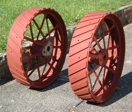
On the left - Pair of finished wheels showing inner and outer faces.
On the right - Wheels as they will appear (just needs the engine
in-between).
|
|
|
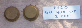
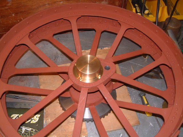
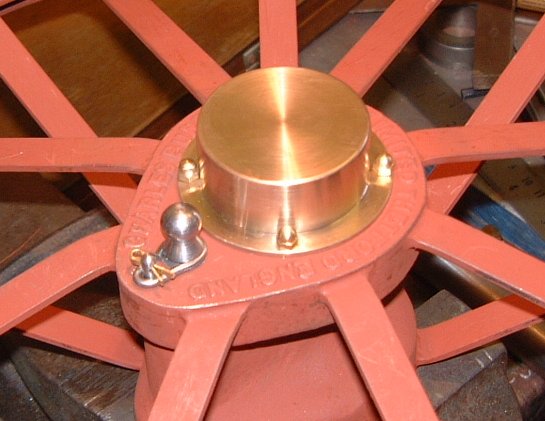
Finally, to finish the wheels off I've added a pair of posh brass
hub caps and driving pins complete with spring retainers and home-made
split pins.
|
|
|